- Posts: 51
- Thank you received: 0
Passive crossovers
- jonny4288
-
 Topic Author
- Offline
- Senior Member
-

Less
More
15 years 5 months ago #9148
by jonny4288
Passive crossovers was created by jonny4288
hey all,
designing a passive crossover at the moment, already have a ultradrive which i will use normally for my midtops, im taking this up as a university project i would like to do.
CP755Ti (8ohm) Resistance 5.5Ohms - 110db 1w/1m
PD123ER (8ohm) Resistance 5.6Ohms - 96db 1w/1m
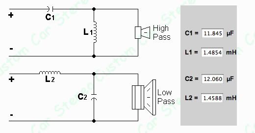
Second Order (12db/octave) Two-Way Crossover
Linkwitz-Riley filter
High pass Impedance - 5.6Ohms
Low pass Impedance - 5.5Ohms
Frequency 1200Hz
Using the above circuit would work however im looking to design something with the option of having a variable crossover if possible, not sure how i would go about this as the only way i can think of doing it is having a great deal of components and a selectable switch to route the signal through the required components for different crossover points.
900Hz is the ideal point i should be crossing but using a 12db LR filter this shifts the -3b point further down than id like it, also have a 180 degree phase shift with this filter, i assume that would mean just reversing the polarity of one or both of the drivers? to bring them back in phase
Also am i correct in getting the D.C resistance of the CD and 12" from the spec sheets as the actual resistance seen across the driver, even though the stated reistance is 8ohms. i rialise this may also change across different frequencies.
I need to also think about adding a lpad to adjust the difference in sensitivity between the 2 drivers as the pd123er is 97db 1w/1m and the cp755ti 110db 1w/1m to get the right balance between mid and top
Will be buying quality components to handle the power. dont want to be melting stuff!! They will for use in a MT121,
Anyone able to help me any further?
had this posted over at sp too but had no responses as of yet,
Please Log in or Create an account to join the conversation.
- tony.a.s.s.
-

- Offline
- Moderator
-

Less
More
- Posts: 1344
- Thank you received: 12
15 years 5 months ago #9153
by tony.a.s.s.
Peace and goodwill to all speaker builders
Replied by tony.a.s.s. on topic Passive crossovers
I build my own crossovers, and because they have a standard building block, I put them together and then adjust when it's connected to the cab. The variable part is harder if you are not an electronics engineer. I had a two way crossover made by my friends in Cambridge with a variable crossover point on the sub, mainly so that I could overlap sub with bass in a passive cab plus sub system. The control knob had a six gang pot behind it the achieve the required slope. Experimentation will teach you the most.
Peace and goodwill to all speaker builders
Please Log in or Create an account to join the conversation.
- Xoc1
-

- Offline
- Senior Member
-

Less
More
- Posts: 51
- Thank you received: 0
15 years 5 months ago #9154
by Xoc1
Replied by Xoc1 on topic Passive crossovers
I think You should read this article on Rob Elliots Website
sound.westhost.com/lr-passive.htm
The phase shift for a butterworth filter means that one ot the drivers at the crossover frequency must be wired up out of phase.
You may find that a 12db slope still lets too much midrange thru your HF driver. Depending on the power level you might have to concider an 18dB filter.
You are not correct to assume that the the impedance is constant over the frequency range. The LF driver will have a rising impedance with frequency and would probably require a Zobel network to correct this.
The HF driver might be OK without impedance compensation especially if it has ferrofluid.
Yes you will need to pad the HF to match the level.
You might concider adding a rising HF response for a constant directivity horn response.
This is why if you want to have a system that performs optimally it is easier to use an active crossover!
Please Log in or Create an account to join the conversation.
Time to create page: 0.314 seconds
