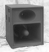
![]() Frequency: from 120 Hz
Frequency: from 120 Hz
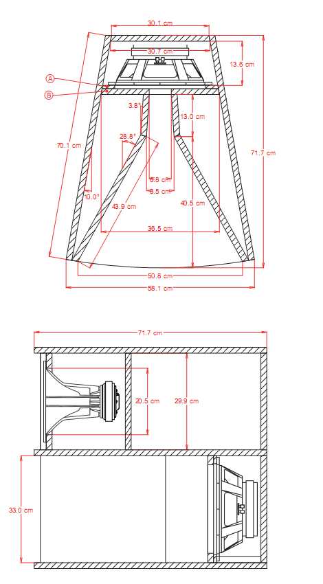
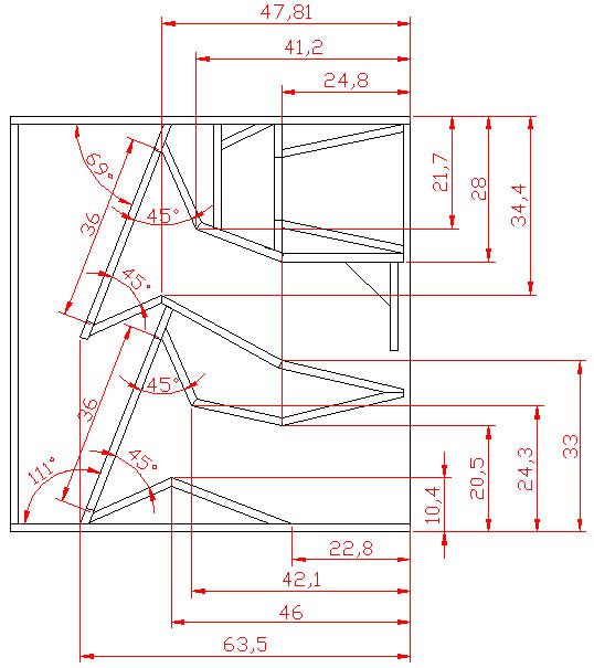
Size: 58x68.3x71cm
Recommended Driver: PD121, Bms 4550 T.data, HF64 Spec Sheet
3D Model:
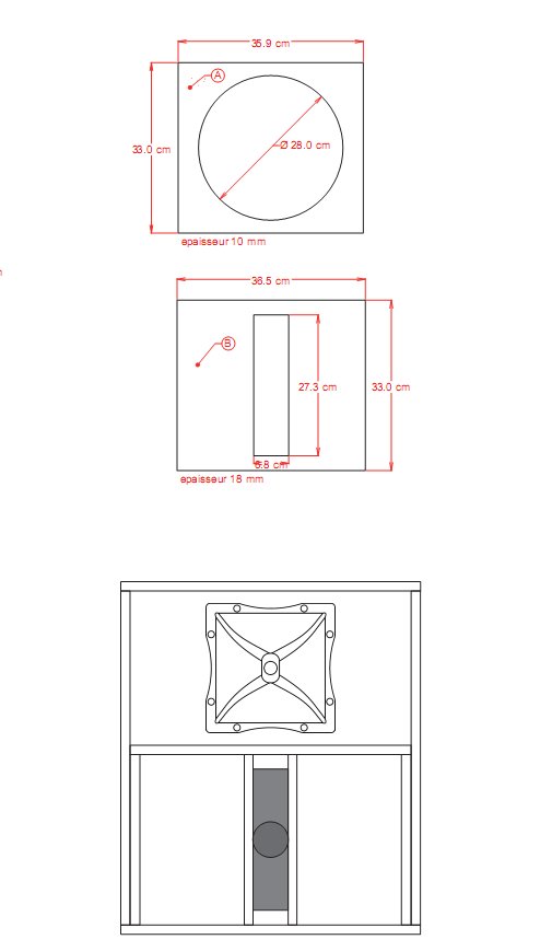
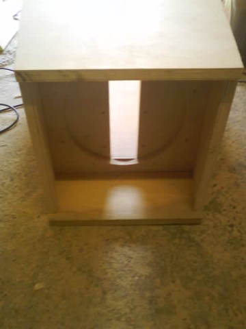
Plan: MT130
Designer:
Discuss this article

This is an interesting model for me, but I have to change:
- BMS 4550 to BMS 4555, because second one is available. The features look like completely the same, that's why it doesn't matter, I think.
- RCF HF64 to BMS 2236, same reason as previous. First one is complicated to buy for me, but possible.
I have to built a crossover also. Which frequency is recommended?

very interested in this design, has anyone made a 15 inch version or could anyone give me the adjusted measurements to make a 15 inch version.
Shane


Just wondering how many sheets of 2440x1220 will be needed for this project and if 18mm sheets are being used?
Also where can i purchase the horn moulding?
Edit: Also wondering if the empty space at the back of the horn, behind the baffle, could be cut out?


seeing the photos it looks like is 15mm all...
Thanks!

Thanks to all!

also, on that note, if they sound good open, ill just leave them that way.
ill post up with pics and my experience soon.

edit*
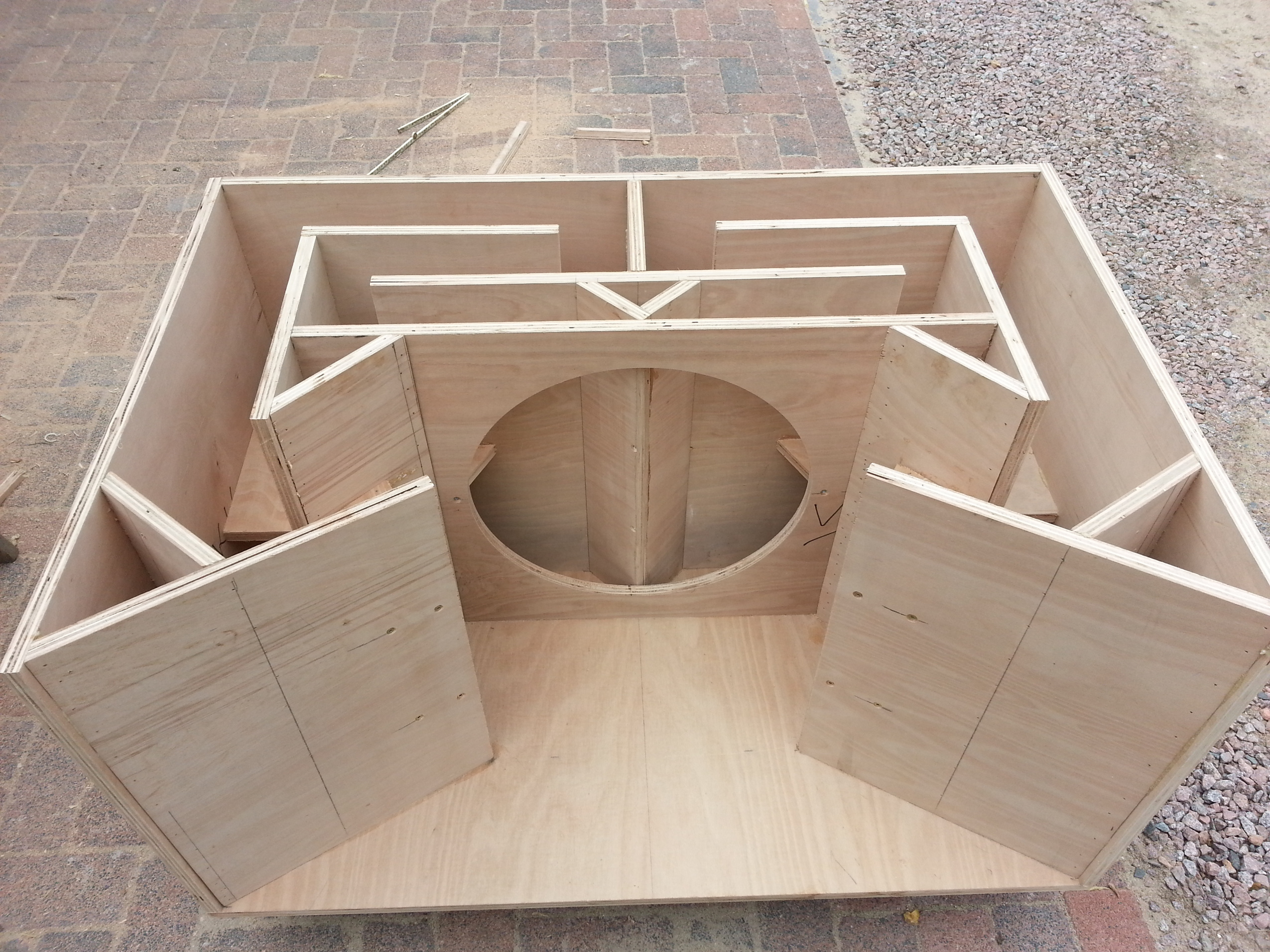
i read the 136mm to be the rear side of the baffle, and ive just reopened the file and discovered that i need to move the baffle forwards. problem there is i have already glued the horn section in place.... dammit.
my biggest Q is wether or not the woofer will act normally with the magnet outside the chamber. (good for cooling tho) as its vented coil. i was thinking i could cut a neat hole, and put a seal around the magnet so the chamber stays sealed.

unless your building the 10" version and trying to stick 12" drivers in it....

just asking as there should be about 13.6cm of depth in that chamber and the delta12 is only 13.6cm deep, the second layer of the baffle that keeps the cone from hitting the 1st slot baffle should only be 1cm deep too.
if it was all made to plan the back of the magnet should be flat against the back of the chamber.

will I be ok to create a hole in the back panel for the magnet to poke out of as long as its sealed?
www.facebook.com/photo.php?fbid=56612031...64333&type=1&theater



rob.parkinson wrote: just finished my build of 4 and I can tell you that with castors and a pair of handles a side they are an easy 2 man lift. weight wise they are a bit hefty for 1, but then they are to big to lift safely alone anyway.
Hey
Can I ask how you got on with these? They're always a design that I've had a bit of an interest in , but only a few people seem to have built them (outside of Marc O's french forum) and always been kind of mixed reviews.
k

klampykixx wrote: any thoughts on the group delay mismatch? do i delay the tops to bring the overall wave as close as possible to each other or do i aim just to get the crossover frequency inline?
hey
yeah measure the delay of your subs and tops each just at the crossover frequency, and then delay so they match at that frequency point.
k

![]()
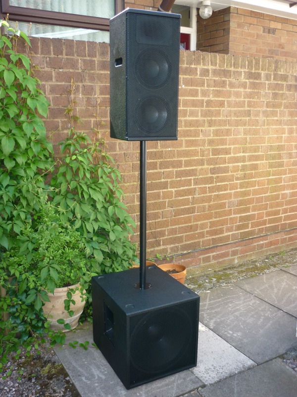
Frequency: 90Hz-15kHz
Enclosure Type: Reflex
Size : 1219x558x558
Recommended Drivers: RCF MB15H401 Spec Sheet & ND850 Spec Sheet or Beyma 15G40E & CP750NdE
Plan:
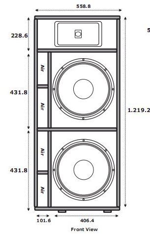

Designer:
Comments from the designer: Hi everybody, Hey this is Prashant from India. I am a sound engg student in Mumbai.
If u wants this design please mail me:-
don’t hesitate & feel free to ask. We are always there for you. Thanks, Prashant.
Discuss this article

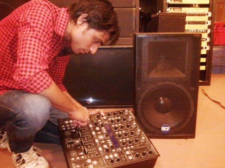
playdjboyes wrote: thanks tony i will try to test all things.
Prashant, I was in no way criticizing you or your design. You have the right to design and make boxes in any way that you like.
I wish you well with your endeavours and hope that you can make a career out of something that you obviously have a passion for.
Tony


With my own boxes I try to minimise the visual aspect by making them as narrow as possible given the driver size and then using wrap around grills. The picture I posted a while ago of my double 12" jobby shows this very well.
For a given box design just net volume and port sizes are all that's required. I think that anyone serious about making loudspeakers should then have learned the necessary skills to take it from there.
Its a bit like taking up golf and then playing St. Andrews without even going for any lessons or spending time on the driving range, not to be advised
Gets of high horse.
Tony
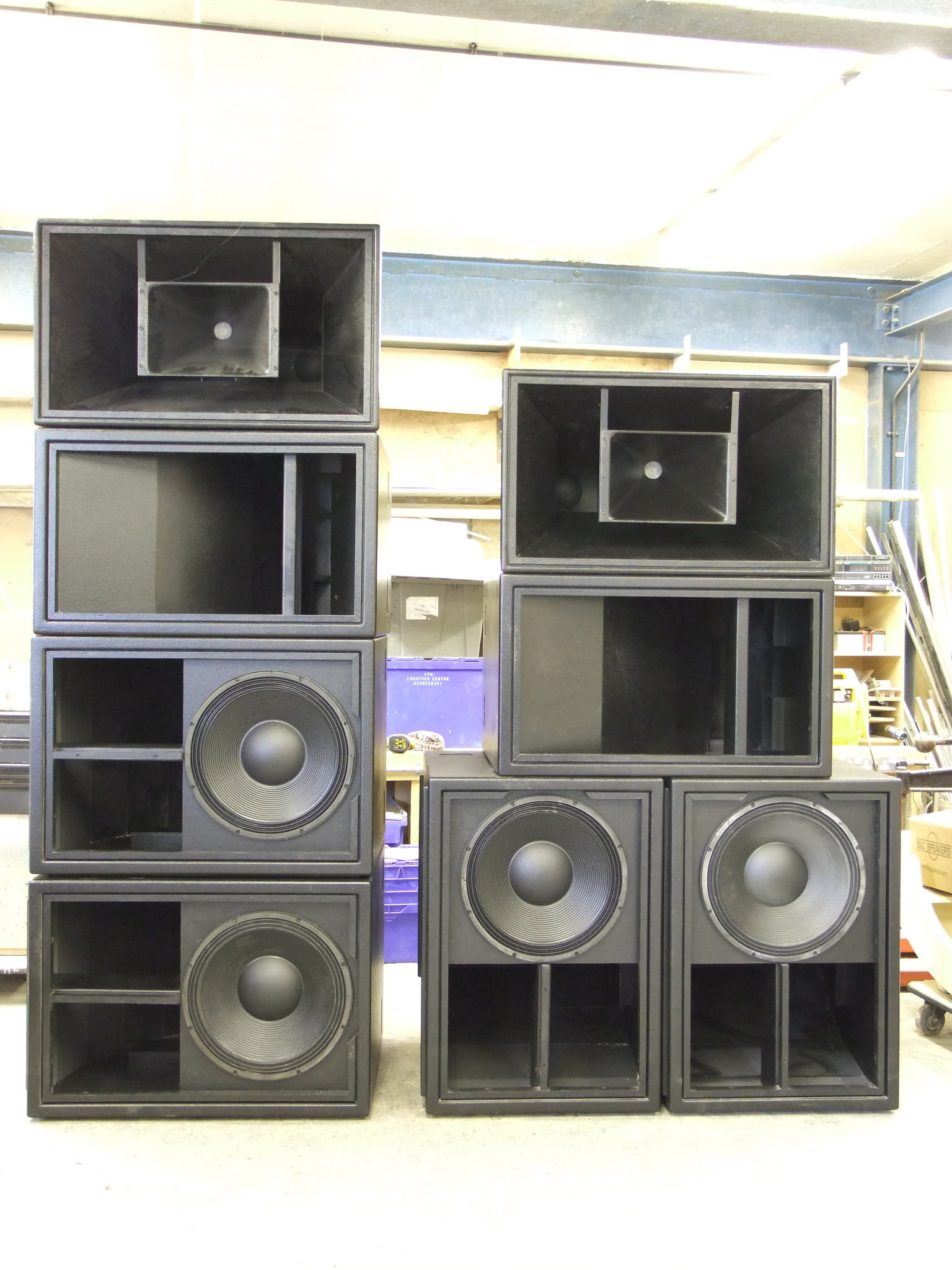
I guess the Spektra range of cabs were the first trap cabs for me, and this was done to follow a fashion.

REQUIRED in New cabinet:- CALCULATING DRIVER PARAMETER & INTERNAL VOLUME LITERS(VB),(FB) also very IMP FREQUENCY TUNNIG.
The word “speaker” is the shortened form of the word “loudspeaker” and it refers to a device that converts electrical signals into sound waves that we can hear.
Why do drivers come in so many different sizes? Because it is nearly impossible to make one piston driver that can reproduce sound waves over the entire 20 Hz to 20 kHz frequency range of human hearing. To produce low frequencies a driver needs to have a large diaphragm and enough mass to resonate at a low frequency. To produce high frequencies a driver needs to have a small diaphragm with a low mass. Obviously, these requirements are in opposition so drivers are usually designed to produce only a portion of the sound. This gives rise to multi-way speaker systems like the two-way system shown above. It uses a tweeter for the high frequencies and a woofer for the low frequencies.
The job of the crossover network is to divide the audio signal. For this reason, crossover networks are sometimes called “dividing networks”. The frequency where the sound is divided is called the “crossover frequency”. Ideally, a crossover frequency is chosen which protects the tweeter, allowing it to produce only those frequencies that it can reproduce the best, and allows both the response and coverage pattern of the woofer to blend well with the tweeter. Note: The “coverage pattern” is the shape of the listening area where a driver will provide a relatively uniform direct sound pressure level.
I m a sound engg student i just learn how to create new idea & discuss with all. any suggestion plz reply me
thanks
As Tony said this is not true. From a performance point of view the difference is negligible, and very very few are designed to be arrayed at the same angle as the side walls. However with a decent table saw it is not too difficult to cut the angles.
Reasons why I use a trapezoid design are:
1. I don't find them much more trouble to make.
2. The shape visually slims the cabinet.
3. I can fix the baffle size and use the taper to adjust the cabinet volume.
4. It sometimes enables a more efficient use of a sheet of ply.
If number 1 didn't apply then I wouldn't worry about 2 and 4, and I would ajust 3, the cabinet volume, by some other means.
For most loudspeaker based on the bass reflex style, plans are not really necessary. An internal volume and tuning frequency should allow anyone to produce something similar. More useful would be any cross over and eq settings. These will have far more impact on the performance of the cabinet than getting the taper angle of the cabinet walls correct.

nickyburnell wrote: Angles would be good. Very trendy all this multi angle stuff, a ton of work though.
I think that for most user's it is a total waste of time. So called reduction in standing waves etc. is IMHO a crock of shyte.
And as for better to array them er no comment.
Tony

Also u can use Beyma 15G40 & CP750ND with 1200Hz passive crossover

Frequency: 90 to 15KHz
Enclosure Type: Horn Loaded midtop![]()
Size: 1030x600x388mm
Recommended Drivers: SN12B, 12ND710 or 12PE32
Plan: SMT212
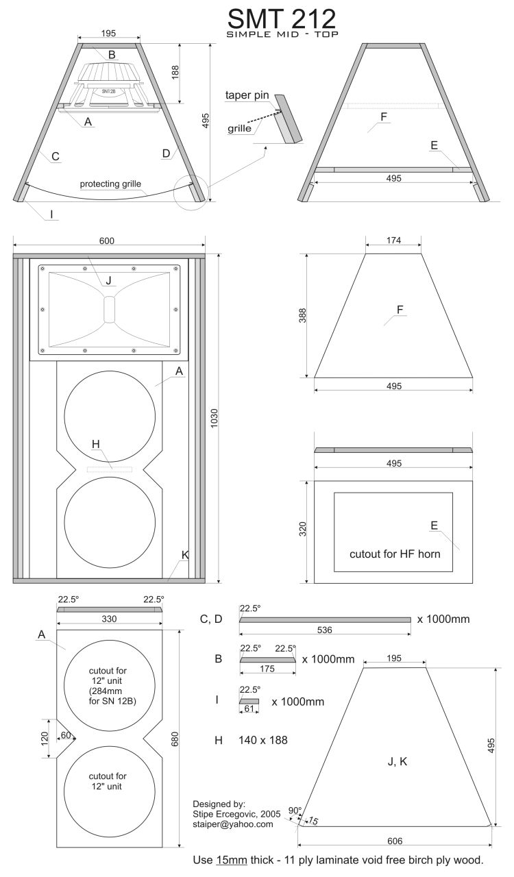
Designer: Stipe Ercegovic (
Discuss this article




Best regards

The thing is that I can´t decide between Beyma 12mi100 or 12p80nd for the midrange drivers.
Is the 12p80nd worth the extra money? How big an advantage dos the 12p80nd have over the 12mi100
- when it comes to sound quality?
- when it comes to max SPL?
Also, will 2 12p80nd working together corse less phase problems than 2 12mi100 working together?
I am planing to use the SMT´s from about 200-250 HZ and up.



At the moment I am designing the plan to cut all the panels
I was wondering if the the 12" driver and the comp driver should be vertically aligned or if a configuration like the attached sketch is fine ( where dark blue 12" driver sits at the back part of the cabinet and the purple comp driver + horn sits a bit forward - drivers are not aligned in this case )
sketch is based on the measures of 18sound 12mb700 12" mid bass driver and Compression P Audio BM-D750 Serie 2 with Horn P Audio PH-3223
This will determine the width/position of the horn baffle.
From other build I've seen on the web it seems that they are not vertically aligned but before I cut the wood I wanted to make sure I am not making any mistake
thank you for any advice !


Does anyone know the maximum frequency response of the 12" section as a single? I was hoping to use them from 200-1.4khz
Thanks


just wondering would this design work well with any 12" fane drivers
i.e 12mbn and 12bmn?
Many Thanks
Ollie
www.precision-devices.com/Product-Details/PDN12MH25 , :blush: sorry guys ihad the wrong model number of the 12" drivers originally. My bad. oops! :blush:

what drivers are best?
Gareth


Frequency: 90Hz to 20KHz
Enclosure Type:Horn
Size:800x500x770mm
![]() Recommended Driver:
Recommended Driver:
2x 15ND930
1x 8PE21
1x DE500
Plan: X-TRO


Settings: 2x Punisher/1x X-tro
Processor settings All filters 24db/oct Linkwitz/Riley s
Sub hp: 40,5 hz (For a single cabinet a side 45Hz can be used) lp: 91,0 hz
low hp: 99,2 hz lp: 297 hz
mid hp: 315 hz lp: 2,38 khz
high hp: 2,45 khz
Delay:
sub 0
low 5,99 ft 1,82 mtr 5,31 msec
mid 6,81 ft 2,07 mtr 6,04 msec
high 7,21 ft 2,19 mtr 6,40 msec
sub1 40-50Hz (depending on number of cabinets) gain: personal taste Q = 3-4 sub2 105 hz -1,0 db Q = 4,410 mid 2,25 khz + 4,0 db Q = 1,215 high 14,3 khz +1,0 db Q = 1,789
Website: http://www.speakerstore.nl/index.php?l=en&pg=11&c=21
Designers: Walt and Frederik from www.speakerstore.nl
Discuss this article

nikkelbatenburg wrote: Hopefully the 15'' do deliver hard kick bass, thats the reason I want to build them. Yes 4 CBe's and 2 X-tro is the idea, maybe I build 2 extra CBe's!
I have just that:-) -Actually the CBes from diskosucks:-)
And I'm considering exactly the same, ehm + 2 xtros:-)
But Discosucks does not have the cnc plans for the subs anymore, anyone?
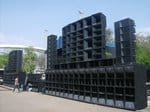
Where can I find the X8 Mk2 flare pls?

I am about to upgrade the the 15" in the h3 to the h3+'s driver ( 400 to 700 watt aes )
But im not sure will this making much of a difference in spl . The same way as i would Imagen your cbe's are just as loud as mine .

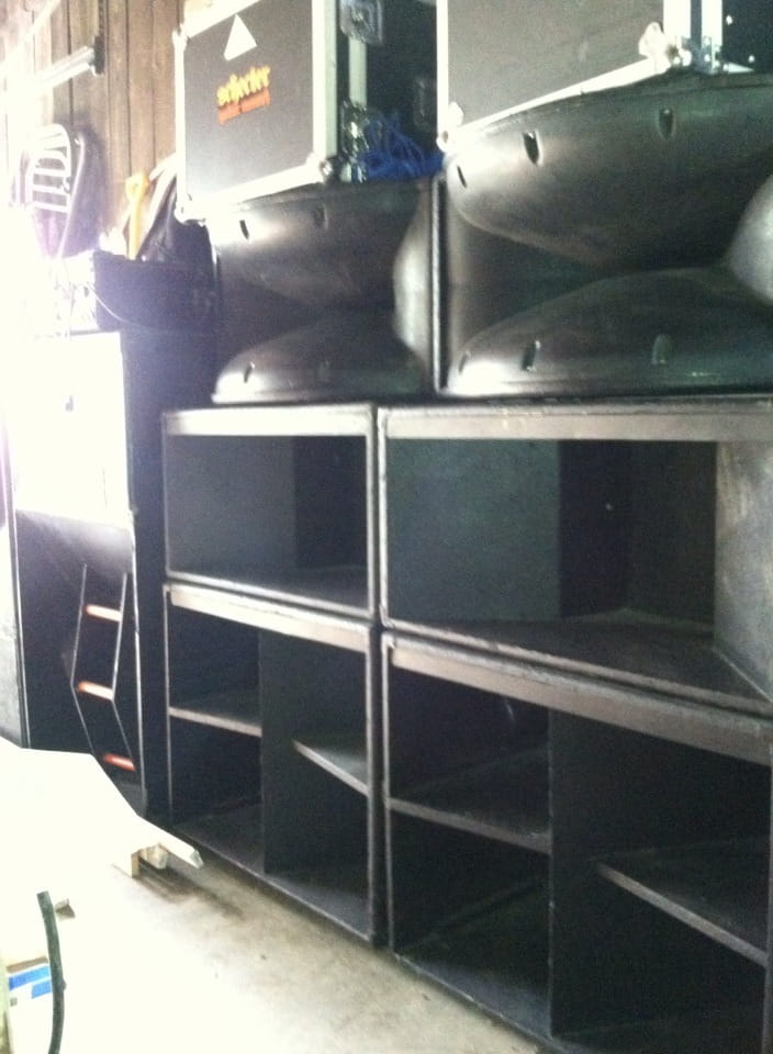
My cbe's are loaded with fane colossus 18 1500 , and they are really loud . I think if i had two more h3's it would be a better mix .


I like the kick / cbe combo but the h3's can get left behind at high spl so i bet the x tro's would work well .


Are the two 15''s designed too deliver hard kick ?
are you planning to use the x tro's with the cbe's in your picture?


I've find the PDF drawings but impossible to find the Autocad parts....
If someone have this in a part of his harddisk...
Thx :mrgreen:
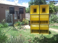


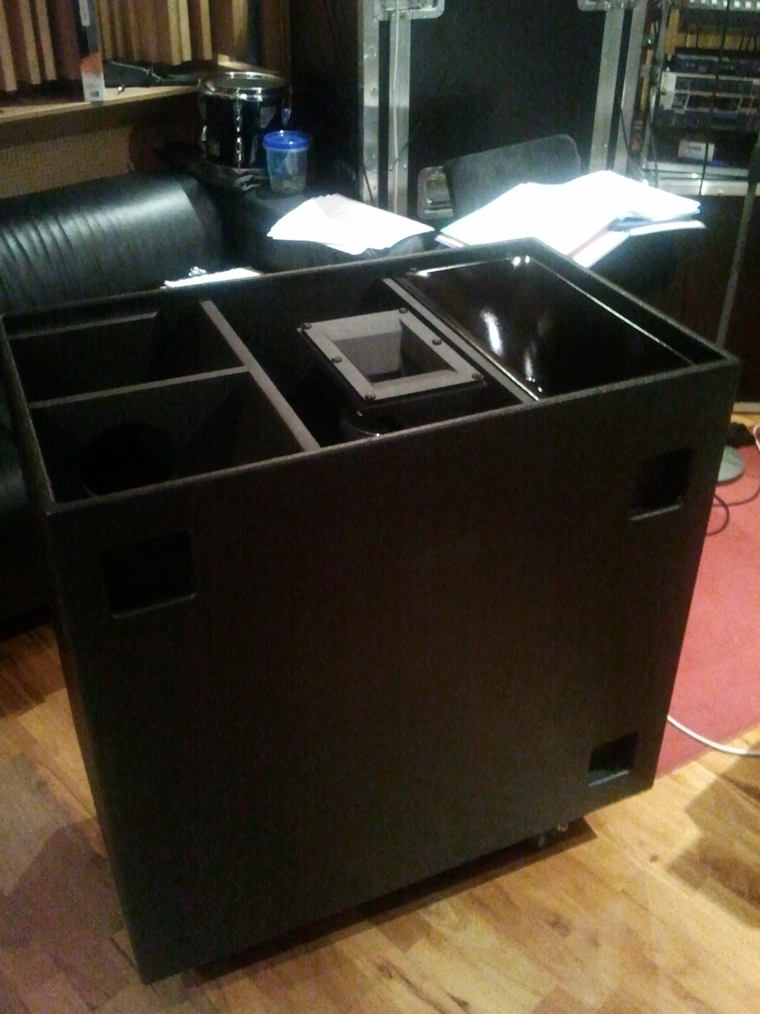

for example take one of the 15" horns then re-design it using a 12" driver, with a 6.5" horn and a 1" hf horn............
nrpinc what you need to remember is the xtro sounds very good as it was designed to sound. By changing its design may indeed make it sound not as good.


